

Product display

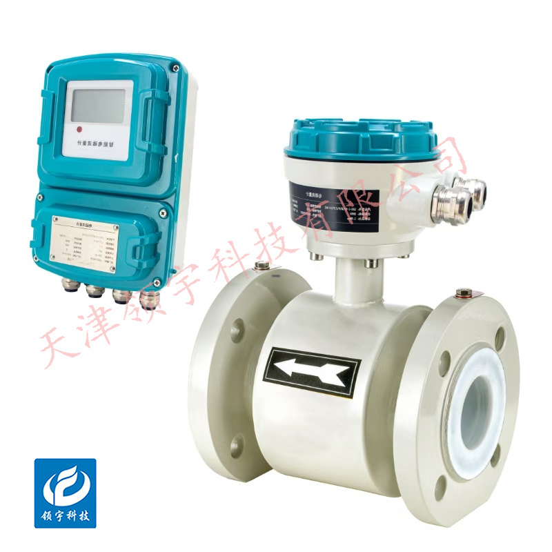
LF-14...Z-Series Split-Type Electromagnetic Flowmeter
● Utilizing SMD components and surface-mount technology (SMT), the circuit boasts high reliability.
● The pipeline contains no moving parts or flow-obstructing components, resulting in virtually no additional pressure loss during measurement.
● Utilizing SMD components and surface-mount technology (SMT), the circuit boasts high reliability.
● The measurement range can be modified online on-site according to the user's actual needs.
● Features digital communication signal outputs such as RS485, RS232, HART, and Modbus Profibus-DP (optional)
Key words:
Classification:
Download information:
Product Description
Product Overview Product overview
The LF-14...Z Series Split-Type Electromagnetic Flowmeter consists of two main components: the sensor and the converter. It operates based on Faraday's law of electromagnetic induction, making it ideal for measuring the volumetric flow rate of conductive liquids—it’s a velocity-type instrument. In addition to accurately measuring the volume flow of common conductive liquids, this flowmeter can also handle highly corrosive fluids such as strong acids and strong bases, as well as uniform liquid-solid two-phase suspensions like mud, mineral slurries, and pulp. Widely used across various industrial sectors—including petroleum, chemical processing, metallurgy, light industry, papermaking, environmental protection, and food production—as well as in municipal management, water conservancy projects, and river dredging operations, the LF-14...Z Series is an essential tool for precise flow measurement in these critical applications.
Performance metrics TECHNICAL PARAMETERS
| Implementation Standards |
Electromagnetic Flowmeter (JB/T9248-1999) |
| Nominal Diameter (mm) (Special specifications available upon request) |
Pipe-type four-flange lining: DN10–DN600 |
| Pipe-type rubber village: DN65–DN2000 |
|
| Flow direction |
Gross, net, and net-of-tax cash flows |
| Measurement range ratio |
20:1 |
| Repetitive error |
Measurement accuracy of ±0.1% |
| Accuracy Level |
Class 0.5, Class 1.0 |
| Measured medium temperature |
Standard rubber lining: -20~+60°C |
| High-temperature rubber lining: -20 to +90°C |
|
| PTFE lining: -30°C to +120°C |
|
| High-temperature PTFE lining: -20°C to +160°C |
|
| Rated working pressure (High-pressure, customizable) |
DN10–DN50 4.0 MPa |
| DN65–DN300 ≤1.6 MPa |
|
| DN350–DN600 1.0 MPa |
|
| DN700–DN2000 ≤ 0.5 MPa |
|
| Flow rate range |
0.5-10m/s |
| Electrical Signal Frequency Range |
The conductivity of the fluid being tested is ≥5 µS/cm |
| Signal output |
4–20mA (load resistance 0–750Ω), pulse/frequency, control level |
| Communication Output |
RS485, MODBUS protocol, HART protocol, Profibus-DP protocol |
| Power supply |
220VAC, with a tolerance of ±15%, or 24VDC, with ripple ≤5%. |
| Request for straight pipe section length |
Upstream = 5 DN, Downstream = 2 DN |
| Connection method |
Flow meters are connected to the piping systems using flanges that comply with the national standard: GB/T 9113.1-2000. |
| Explosion-proof rating |
Exd[ib]qII CT6 Gb |
| Protection Level |
IP65, custom-made options available up to IP68 |
| Ambient temperature |
-25 to +60°C |
| Relative humidity |
5% to 95% |
| Total Power Consumption |
Less than 20W |
How it works Working Principle
According to Faraday's law of electromagnetic induction, a pair of detection electrodes is installed on the pipe wall perpendicular to both the axis of the measuring tube and the magnetic field lines. When a conductive liquid flows along the axis of the measuring tube, it cuts through the magnetic field lines, generating an induced electromotive force. This induced voltage is detected by the two electrodes, and its magnitude is directly proportional to the flow rate—specifically, the value is
E = B · V · D · K
Where: E – Induced electromotive force
K—A coefficient related to the magnetic field distribution and axial length,
B - Magnetic Induction Intensity
V - Average flow velocity of the conductive liquid
D- Electrode spacing; (measured inner diameter of the tube)
The sensor detects the electromotive force E as a flow signal and transmits it to the converter. After undergoing a series of digital processing steps—including amplification, transformation, and filtering—the signal is displayed on a backlit dot-matrix LCD, showing both instantaneous and cumulative flow rates. The converter features 4–20 mA output, alarm output, and frequency output, along with communication interfaces such as RS-485, and supports HART and MODBUS protocols.

External dimensions APPEARANCE OF SIZE

| Sensor mounting dimensions | ||||||||
| Nominal Diameter (mm) |
L (mm) |
D (mm) |
K (mm) |
H (mm) |
H (mm) |
nxd (mm) |
Withstand Voltage Rating | Specially designed for high pressure Level |
| 10 | 120 | 60 | 60 | 260 | 190 | 4 × 14 | 4MPa | Below 16 MPa |
| 15 | 200 | 95 | 65 | 310 | 240 | 4 × 14 | ||
| 20 | 200 | 105 | 75 | 315 | 245 | 4 × 14 | ||
| 25 | 200 | 115 | 85 | 325 | 255 | 4 × 14 | ||
| 32 | 200 | 140 | 100 | 325 | 255 | 4 × 18 | ||
| 40 | 200 | 150 | 110 | 340 | 270 | 4 × 18 | ||
| 50 | 200 | 165 | 125 | 355 | 285 | 4 × 18 | ||
| 65 | 200 | 185 | 145 | 375 | 305 | 4 × 18 | 1.6MPa | 4.0MPa |
| 80 | 200 | 200 | 160 | 385 | 315 | 8 × 18 | ||
| 100 | 250 | 220 | 180 | 415 | 325 | 8 × 18 | ||
| 125 | 250 | 250 | 210 | 445 | 355 | 8 × 18 | ||
| 150 | 300 | 285 | 240 | 475 | 385 | 8 × 22 | ||
| 200 | 350 | 340 | 295 | 505 | 415 | 12 × 22 | ||
| 250 | 450 | 405 | 355 | 590 | 500 | 12 × 22 | ||
| 300 | 500 | 460 | 410 | 645 | 555 | 12 × 22 | ||
| 350 | 500 | 505 | 460 | 695 | 605 | 16 × 22 | 1.0MPa | 2.5MPa |
| 400 | 600 | 565 | 515 | 745 | 655 | 16 × 26 | ||
| 450 | 600 | 615 | 565 | 825 | 735 | 20 × 26 | ||
| 500 | 600 | 670 | 620 | 878 | 788 | 20 × 26 | ||
| 600 | 600 | 780 | 725 | 988 | 898 | 20 × 30 | ||
| 700 | 700 | 860 | 810 | 1095 | 1005 | 24 × 30 | 0.6MPa | 1.0MPa |
| 800 | 800 | 975 | 920 | 1208 | 1138 | 24 × 34 | ||
| 900 | 900 | 1075 | 1020 | 1310 | 1220 | 28 × 34 | ||
| 1000 | 1000 | 1175 | 1120 | 1413 | 1323 | 28 × 36 | ||
| 1200 | 1200 | 1405 | 1340 | 1525 | 1435 | 32 × 33 | ||
| 1400 | 1400 | 1630 | 1560 | 1735 | 1645 | 36 × 36 | ||
| 1600 | 1600 | 1830 | 1760 | 1965 | 1875 | 40 × 36 | ||
| 1800 | 1800 | 2045 | 1970 | 2155 | 2065 | 44 × 39 | ||
| 2000 | 2000 | 2265 | 2180 | 2365 | 2275 | 48 × 42 | ||
Note: H* refers to the height of the split-type electromagnetic flowmeter sensor.
This instrument's height is measured based on the dimensions of the LDG (integrated) converter and is provided for reference only. For precise details, please contact our sales team.
Installation Requirements INSTALLATION

Avoid air bubbles. If air bubbles enter the flow tube, the flow reading will be affected, potentially leading to measurement errors. When fluids contain air bubbles, the pipeline design must prevent bubble accumulation inside the flow meter tube. If valves are located near the flow tube, arrange the pipe upstream of the valve whenever possible to avoid pressure drops that could cause bubble formation.
To ensure the flowmeter operates reliably and stably, the following considerations should be taken into account when selecting the installation location:
⑴ Avoid magnetic objects and equipment with strong electromagnetic fields (such as large motors, big transformers, etc.) as much as possible, to prevent magnetic fields from interfering with the sensor's operating magnetic field and flow signal.
(2) It should be installed in a dry, well-ventilated area whenever possible, and is not suitable for installation in damp or water-prone locations.
⑶ Avoid direct exposure to sunlight and rain whenever possible, and ensure the ambient temperature does not exceed 60°C or the relative humidity exceeds 95%.
⑷ Choose a location that is easy to maintain and provides convenient access for maintenance activities.
⑸ The flowmeter should be installed at the downstream end of the pump, and must never be placed on the suction side; the valve should be mounted on the downstream side of the flowmeter.
Previous Page
Previous Page
Related Products
Product inquiry
If you are interested in our products, please leave your e-mail, we will contact you as soon as possible, thank you!
Tianjin Ling Yu Technology Co., Ltd.
Operator:86-22-58554679
Fax: 022-58285528
Manager Ding: 86-18902041592
WhatsApp:8618902041592
Complaint Hotline:86-15822286986
Factory Address: No.5 Yingbin Road, Xiqing District, Tianjin
E-mail:sales@lingyukeji.com
Purchasing Department E-mail:lykj_tj@163.com
WhatsApp Scan

Copyright©2022 Tianjin Ling Yu Technology Co., Ltd