

Product display

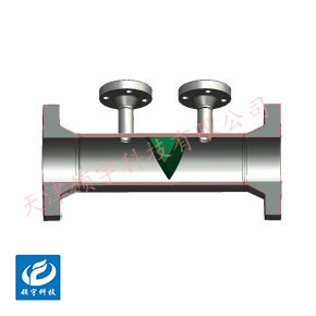
LF-19X Wedge Flow Meter
● Wide applicability: Particularly adept at measuring high-viscosity or impurity-laden fluids such as crude oil, asphalt, pulp, and mud; also suitable for use with conventional gases and liquids.
● Strong anti-clogging capability: The wedge-shaped throttling element features no sharp dead corners between itself and the pipeline, preventing solid particles or viscous media in the fluid from easily accumulating, thus extending the maintenance cycle.
●Low installation requirements: The length of the straight pipe sections required upstream and downstream is significantly shorter than that for standard orifice plates (typically just 5D upstream and 2D downstream, where D represents the pipe diameter), saving valuable installation space.
Key words:
Classification:
Download information:
Product Description
Product Overview Product overview
The LF-19X series wedge flowmeter is a new type of differential-pressure flowmeter independently developed by our company, built upon the foundation of digesting and absorbing advanced foreign wedge sensor technology for flow measurement. This innovative product matches the performance of cutting-edge international technologies while addressing key limitations such as a narrow rangeability, significant pressure loss, and stringent Reynolds number requirements. It is ideally suited for flow measurement and process control across industries including petroleum, chemical processing, natural gas, metallurgy, steel production, power generation, water resources, pharmaceuticals, textiles, beverages, energy, environmental protection, and municipal utilities.
Performance metrics TECHNICAL PARAMETERS
| Tested medium |
Medium- to high-flow-rate media such as steam, compressed air, coal gas, and liquids |
|||
| Implementation Standards |
Vortex Shedding Flow Sensor (JB/T9249-2015) |
|||
| Verification Procedure |
Vortex Flow Meter (JG1029-2007) |
|||
| Instrument diameter (mm) and connection method
|
Flange-connected type |
DN15-DN300 |
||
| Clip-mounted connection type |
DN15-DN300 |
|||
| Accuracy Level |
Liquid: ±1%; Gas or vapor: ±1.5%, ±1% |
|||
| Measurement range ratio |
1:10; 1:15; 1:20 |
|||
| Sensor material |
304 stainless steel, 316 stainless steel, and more |
|||
| Terms of Use |
Media temperatures: -40°C to +70°C, -40°C to +250°C, -40°C to +350°C Ambient temperature: -20°C to +60°C Relative humidity: 5%–90% Atmospheric pressure: 86 kPa to 106 kPa |
|||
| Signal output function |
Pulse signals, 4–20mA signals |
|||
| Communication Output Function |
RS485 communication, HART protocol, and more |
|||
| Working power |
A. External Power Supply: +24VDC ±15%, Ripple ≤ ±5%, suitable for 4-20mA output, pulse output, RS485, and more B. Internal Power Supply: 1 set of 3.0V, 10AH lithium batteries, which can operate normally when the battery voltage ranges from 2.0V to 3.0V. |
|||
| Flange Standards |
Standard specifications |
GB/T 9113-2000 |
||
| Other standards |
International Pipe Flanges |
For example: German standard DIN, American standard ANSI, Japanese standard JIS |
||
| Domestic Pipe Flanges |
For example: Standards of the Ministry of Chemical Industry, Standards of the Ministry of Machinery |
|||
| Electrical interface |
M20×1.5 internal thread (NPT threads require customization) |
|||
| Explosion-proof rating |
ExdIICT6 Gb |
|||
| Protection Level |
IP65 or higher (customizable) |
|||
How it works Working Principle
The measurement principle of the LF-19 series wedge flowmeters is based on a flow measurement method founded on the law of energy conservation—specifically, Bernoulli’s equation—and the principle of fluid continuity. When a fluid flowing through a pipe passes by the wedge-shaped flowmeter, the flow stream contracts, causing the flow velocity to increase while the static pressure decreases. This creates a static pressure difference ΔP between the upstream and downstream sides of the wedge-shaped throttling element. The magnitude of this pressure difference ΔP is directly related to the fluid’s flow rate Q. This relationship can be calculated using the following basic formula:
Mass flow rate:

Volumetric flow rate:

Where:
q m ---- Mass flow rate, kg/s
q v ---- Volumetric flow rate under working conditions, m³ 3 /s
C ---- Discharge Coefficient
ε---- Coefficient of expansibility (expansion)
m ---- Throttle area ratio, m = S 1 / πD 2 /4
D ---- Pipe inner diameter under working conditions, m
S 1 ---- Under working conditions, arc-shaped flow area, m 2
ρ 1 ---- Fluid density under working conditions, kg/m³ 3
ΔP ---- Differential pressure, Pa
External dimensions APPEARANCE OF SIZE

| Flange Connection Type Dimension Comparison Chart | |||||||||
| Instrument diameter (mm) |
L (mm) |
D (mm) |
K (mm) |
H(mm) | d (mm) |
n (Number of holes) |
Bolt specifications | Standard configuration Pressure-resistant |
|
| Pulse Output Type | Smart-type | ||||||||
| 15 | 180 | 95 | 65 | 415 | 440 | 14 | 4 | M12×60 | Φ18 × 1.5 |
| 20 | 180 | 105 | 75 | 420 | 445 | 14 | 4 | M12×60 | Φ25 × 2.5 |
| 25 | 180 | 115 | 85 | 425 | 450 | 14 | 4 | M12×60 | Φ32 × 3.5 |
| 32 | 180 | 140 | 100 | 435 | 460 | 18 | 4 | M16×70 | Φ39 × 3.5 |
| 40 | 180 | 150 | 110 | 435 | 455 | 18 | 4 | M16×70 | Φ48×4 |
| 50 | 180 | 165 | 125 | 460 | 480 | 18 | 4 | M16×70 | Φ59 × 4.5 |
| 65 | 200 | 185 | 145 | 470 | 500 | 18 | 4 | M16×70 | Φ74 × 4.5 |
| 80 | 200 | 200 | 160 | 490 | 520 | 18 | 8 | M16×70 | Φ89 × 4.5 |
| 100 | 200 | 220 | 180 | 515 | 545 | 18 | 8 | M16×70 | Φ109 × 4.5 |
| 125 | 220 | 250 | 210 | 535 | 560 | 18 | 8 | M16×70 | Φ134 × 4.5 |
| 150 | 220 | 285 | 240 | 570 | 595 | 22 | 8 | M16 × 90 | Φ159 × 4.5 |
| 200 | 220 | 340 | 295 | 625 | 650 | 22 | 12 | M16 × 90 | Φ219 × 9 |
| 250 | 250 | 405 | 355 | 685 | 710 | 26 | 12 | M24×110 | Φ273 × 11 |
| 300 | 300 | 460 | 410 | 710 | 735 | 26 | 12 | M24×110 | Φ325 × 12 |
Note: ① All the above parameters apply to vortex flowmeters with a pressure rating of 1.6 MPa and flanged connections.
② The flanged vortex flowmeter is delivered from the factory without pipe flanges and bolts, which must be purchased separately by the user. The connecting flanges comply with the GB/T 9113-2000 standard for raised-face, flat-welded steel pipe flanges.
Installation Requirements INSTALLATION
1. The wedge flowmeter can be directly installed and used on either horizontal or vertical pipelines. The inner walls of the process pipe should be smooth, clean, and free of any deposits. Installation is recommended on horizontal pipelines to avoid the hassle of zero-point adjustment.
2. When measuring liquid flow in a vertical pipe, to prevent the pipe from being partially filled with fluid, the fluid should flow from bottom to top. Since the positive and negative pressure taps are not at the same horizontal level, the height difference between them must be properly accounted for—either by adjusting the "zero point" of the differential pressure transmitter or by setting the "migrating amount."
3. When installing a wedge flowmeter for measuring liquids, ensure that the differential pressure transmitter can easily vent any air bubbles to prevent zero-point drift in the instrument.
4. For specialized wedge flowmeters (wear-resistant and corrosion-resistant types), care should be taken to protect the internal flow passages and flange sealing surfaces during disassembly, handling, and maintenance, ensuring that the coating remains undamaged.
5. Straight pipe sections should be installed upstream and downstream of the wedge flowmeter. If the actual straight pipe lengths are less than half of the recommended values, additional measurement errors may increase by 0.5% to 1%. The recommended lengths for these straight sections are shown in the figure below.

Previous Page
Next Page
Previous Page
Next Page
Related Products
Product inquiry
If you are interested in our products, please leave your e-mail, we will contact you as soon as possible, thank you!
Tianjin Ling Yu Technology Co., Ltd.
Operator:86-22-58554679
Fax: 022-58285528
Manager Ding: 86-18902041592
WhatsApp:8618902041592
Complaint Hotline:86-15822286986
Factory Address: No.5 Yingbin Road, Xiqing District, Tianjin
E-mail:sales@lingyukeji.com
Purchasing Department E-mail:lykj_tj@163.com
WhatsApp Scan

Copyright©2022 Tianjin Ling Yu Technology Co., Ltd