

Product display

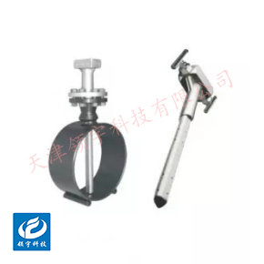

LF-19B2 Series Ball-Type Flow Meters
● High-temperature and high-pressure resistance: Ranges from -80°C to +200°C, with pressure capacity up to 10 MPa
● Suitable for various diameters: φ15–φ1500mm
● Suitable for measuring highly viscous media containing sediment and sand
● Multiple installation options available: clamp-type, flange-type, threaded-type, insertion-type, detachable insertion-type, sanitary-type, and integrated/segmented designs.
Key words:
Classification:
Download information:
Product Description
Product Overview Product overview
The LF-19B2 series of turbine flowmeters builds upon the traditional isolated-diaphragm target flowmeter by integrating a novel strain sensor into the design. Combined with the latest digital and microelectronic technologies, these flowmeters process the sensed signals into a 4–20 mA output proportional to the flow rate. Additionally, they feature a dual-row large LCD display that simultaneously shows both instantaneous and cumulative flow rates, significantly enhancing both the structural design and performance of conventional target flowmeters. This model is particularly well-suited for measuring complex fluids with high viscosity, low Reynolds numbers, or those containing suspended particles.
Performance metrics TECHNICAL PARAMETERS
| Accuracy | ±0.5% to ±2.5% FS, Standard Model: ±1.0% FS |
| Medium temperature | -40℃ to +200℃ (for temperatures above 100℃, use a heat sink; for temperatures exceeding +200℃ or below -30℃, install a jacketed system) |
| Ambient temperature | -40°C to +85°C (the LCD will not be damaged); the LCD operates normally between -30°C and +80°C. |
| Power supply | 24VDC two-wire 4–20mA (12VDC–32VDC) Battery type: 3.6V @ 7.5Ah lithium battery, providing up to three years of continuous use |
| Output signal | 4–20mA |
| Measurement tube material | Stainless steel 304, 316, or other |
| Explosion-proof marking | Intrinsically safe ExiallCT5, flameproof ExdIIBT6 |
| Cable interface | Explosion-proof 1/2 NPT internal thread, with other M20 × 1.5 internal threads. |
| Liquid Crystal Display | Instantaneous flow display range: 0–50,000 (with or without decimal points) Cumulative flow display range: 0–99,999,999 (with or without decimal points), auto-resetting |
| Shell Material | Cast aluminum |
| Load Characteristics | RLmax = 50 × (Supply Voltage - 12)² @ 24V |
| Protection Level | IP65 |
How it works Working Principle
1. Structure
The intelligent target flowmeter consists of: 1) the transmitter housing, 2) the elastic tube sensor, 3) the target rod, 4) the target plate, and 5) the measuring tube. Depending on the specific process conditions of the medium being measured, it is essential to select appropriate elastic tube sensors, target rods, target plates, and measuring tube configurations. Therefore, users must provide accurate and comprehensive process parameters, as this information is critical for ensuring optimal instrument performance.

2. How it Works
When the medium flows through the measuring tube, it strikes the target plate, generating an impact force F on the plate. This force is then transmitted via the target plate rod to the elastic-tube sensor, causing the sensor to experience a force whose magnitude is related to the flow velocity V, the medium’s density ρ, and the target plate’s effective area A—specifically, the relationship can be expressed as follows:
F = CAρV² / 2g
In the formula:
F: Force acting on the target plate
C: Drag coefficient
A: Area of the target plate in contact with the force
ρ: Fluid density
V²/2g: Characteristic flow velocity
where V: Fluid velocity
It is evident that, given a fixed target plate, the specific medium flow velocity is directly proportional to the square root of the force experienced by the target plate. In other words: V ∝ √F. Consequently, under constant measuring tube conditions, the medium flow rate Q is also proportional to F. Additionally, the force exerted on the elastic-tube sensor—directly corresponding to its electrical signal output—is further amplified by a preamplifier, processed through an A/D converter, a microprocessor, and finally converted into a D/A device, ultimately yielding a 4–20 mA signal output that is linearly proportional to the medium flow rate.
External dimensions APPEARANCE OF SIZE

| Flange Connection Type Dimension Comparison Chart | |||||||||
| Instrument diameter (mm) |
L (mm) |
D (mm) |
K (mm) |
H(mm) | d (mm) |
n (Number of holes) |
Bolt specifications | Standard configuration Pressure-resistant |
|
| Pulse Output Type | Smart-type | ||||||||
| 15 | 180 | 95 | 65 | 415 | 440 | 14 | 4 | M12×60 | Φ18 × 1.5 |
| 20 | 180 | 105 | 75 | 420 | 445 | 14 | 4 | M12×60 | Φ25 × 2.5 |
| 25 | 180 | 115 | 85 | 425 | 450 | 14 | 4 | M12×60 | Φ32 × 3.5 |
| 32 | 180 | 140 | 100 | 435 | 460 | 18 | 4 | M16×70 | - Install strictly according to the arrow指示 on the flow meter housing; do not reverse the installation. |
| 40 | 180 | 150 | 110 | 435 | 455 | 18 | 4 | M16×70 | Φ48×4 |
| 50 | 180 | 165 | 125 | 460 | 480 | 18 | 4 | M16×70 | Φ59 × 4.5 |
| 65 | 200 | 185 | 145 | 470 | 500 | 18 | 4 | M16×70 | Φ74 × 4.5 |
| 80 | 200 | 200 | 160 | 490 | 520 | 18 | 8 | M16×70 | Φ89 × 4.5 |
| 100 | 200 | 220 | 180 | 515 | 545 | 18 | 8 | M16×70 | Φ109 × 4.5 |
| 125 | 220 | 250 | 210 | 535 | 560 | 18 | 8 | M16×70 | Φ134 × 4.5 |
| 150 | 220 | 285 | 240 | 570 | 595 | 22 | 8 | M16 × 90 | Φ159 × 4.5 |
| 200 | 220 | 340 | 295 | 625 | 650 | 22 | 12 | M16 × 90 | Φ219 × 9 |
| 250 | 250 | 405 | 355 | 685 | 710 | 26 | 12 | M24×110 | Φ273 × 11 |
| 300 | 300 | 460 | 410 | 710 | 735 | 26 | 12 | M24×110 | Φ325 × 12 |
Note: ① All the above parameters apply to vortex flowmeters with a pressure rating of 1.6 MPa and flanged connections.
② The flanged vortex flowmeter is delivered without pipe flanges and bolts, which must be purchased separately by the user. The connecting flange complies with the GB/T 9113-2000 standard for raised-face, flat-welded steel pipe flanges.
Installation Requirements INSTALLATION
1. Installation Location
- It can be installed horizontally, vertically, or at an angle; horizontal installation is recommended for easier maintenance.
- When installed vertically, the fluid must flow from bottom to top, ensuring the target plate remains at the center of the flow stream.
- Avoid installing at the highest point of the pipe (where air tends to accumulate) or the lowest point (where liquid is likely to collect).
2. Straight Pipe Sections Before and After
- Extremely low requirements for straight pipe sections are its biggest feature.
- Upstream typically requires only 3–5 times the pipe diameter (D), while downstream needs just 1–2 times the pipe diameter (D).
- Still maintains high accuracy even when positioned close to pumps, valves, or bends.
3. Flow and Connectivity
- Install strictly according to the arrow指示 on the flow meter housing; do not reverse the installation.
- Ensure concentricity during flange connections to prevent pipe stress from being transferred to the flowmeter body.
- Thoroughly clean the pipes before installation to remove welding slag, debris, and other impurities.
Previous Page
Next Page
Previous Page
Next Page
Related Products
Product inquiry
If you are interested in our products, please leave your e-mail, we will contact you as soon as possible, thank you!
Tianjin Ling Yu Technology Co., Ltd.
Operator:86-22-58554679
Fax: 022-58285528
Manager Ding: 86-18902041592
WhatsApp:8618902041592
Complaint Hotline:86-15822286986
Factory Address: No.5 Yingbin Road, Xiqing District, Tianjin
E-mail:sales@lingyukeji.com
Purchasing Department E-mail:lykj_tj@163.com
WhatsApp Scan

Copyright©2022 Tianjin Ling Yu Technology Co., Ltd