

Product display

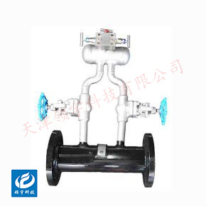
LF-19P Series Nozzle Flow Meters
●Low pressure loss and excellent energy-saving performance: Compared to traditional orifice plates, the nozzle's streamlined design effectively minimizes vortex formation.
● Anti-clogging and wear-resistant with a robust structure: The internal design features no complex components, making the throttling edges highly resistant to wear. Its design prevents debris buildup, making it ideal for handling dirty media containing small particles—and ensuring an exceptionally long service life.
● High measurement accuracy and stable performance: Measurement accuracy typically ranges from ±0.5% to ±2% of full scale, with minimal impact from fluid viscosity and flow velocity fluctuations, ensuring consistent and reliable measurements across a wide flow range.
● Wide range of applicable conditions: It can measure various media such as liquids, gases, and steam, making it particularly suitable for high-temperature, high-pressure, and high-flow applications. It is widely used in industries like power generation, chemical processing, and petroleum.
Key words:
Classification:
Download information:
Product Description
Product Overview Product overview
The LF-19P series nozzle flowmeter is a differential-pressure flow measurement instrument based on the throttling principle, with its core component being a specially curved nozzle. By installing the nozzle directly into the pipeline, the flowing fluid creates a pressure difference as it passes through, enabling precise calculation of the flow rate. As the fluid flows through the nozzle, it gradually contracts at the inlet, accelerating and causing a drop in static pressure. At the throat section immediately downstream of the nozzle outlet, the fluid reaches its maximum velocity while the static pressure drops to its lowest point. By measuring the pressure difference before and after the nozzle—and factoring in fluid density, temperature, and other relevant parameters—it becomes possible to calculate both the instantaneous and cumulative flow rates using Bernoulli’s equation. Thanks to its streamlined design, the nozzle minimizes turbulence at the throttling point, making it less sensitive to solid particles in the fluid and significantly enhancing its resistance to clogging. This makes it particularly well-suited for measuring dirty or slightly impure fluids. The LF-19P series is widely used across industries such as power generation, chemical processing, and petroleum, especially for applications involving steam, gases, and high-viscosity liquids.
Performance metrics TECHNICAL PARAMETERS
| Tested medium |
Medium- to high-flow-rate media such as steam, compressed air, coal gas, and liquids |
|||
| Implementation Standards |
Vortex Shedding Flow Sensor (JB/T9249-2015) |
|||
| Verification Procedure |
Vortex Flow Meter (JG1029-2007) |
|||
| Instrument diameter (mm) and connection method
|
Flange-connected type |
DN15-DN300 |
||
| Clip-mounted connection type |
DN15-DN300 |
|||
| Accuracy Level |
Liquid: ±1%; Gas or vapor: ±1.5%, ±1% |
|||
| Measurement range ratio |
1:10; 1:15; 1:20 |
|||
| Sensor material |
304 stainless steel, 316 stainless steel, and more |
|||
| Terms of Use |
Media temperatures: -40°C to +70°C, -40°C to +250°C, -40°C to +350°C Ambient temperature: -20°C to +60°C Relative humidity: 5%–90% Atmospheric pressure: 86 kPa to 106 kPa |
|||
| Signal Output Function |
Pulse signals, 4–20mA signals |
|||
| Communication Output Function |
RS485 communication, HART protocol, and more |
|||
| Working power |
A. External Power Supply: +24VDC ±15%, Ripple ≤ ±5%, suitable for 4-20mA output, pulse output, RS485, and more B. Internal Power Supply: 1 set of 3.0V, 10Ah lithium batteries, which can operate normally when the battery voltage ranges between 2.0V and 3.0V. |
|||
| Flange Standards |
Standard specifications |
GB/T 9113-2000 |
||
| Other standards |
International Pipe Flanges |
For example: German standard DIN, American standard ANSI, Japanese standard JIS |
||
| Domestic Pipe Flanges |
For example: Standards of the Ministry of Chemical Industry, Standards of the Ministry of Machinery |
|||
| Electrical interface |
M20×1.5 internal thread (NPT threads require customization) |
|||
| Explosion-proof rating |
ExdIICT6 Gb |
|||
| Protection Level |
IP65 or higher (customizable) |
|||
How it works Working Principle
When a fluid flows through a nozzle, it gradually narrows at the inlet, causing the flow velocity to increase while the static pressure decreases. At the throat region immediately downstream of the nozzle exit, the flow velocity reaches its maximum, and the static pressure drops to its lowest point. By measuring the pressure difference before and after the nozzle—and combining this with the fluid’s density, temperature, and other relevant parameters—it’s possible to calculate the fluid’s instantaneous and cumulative flow rates using Bernoulli’s equation.
External dimensions APPEARANCE OF SIZE

| Flange Connection Type Dimension Comparison Chart | |||||||||
| Instrument diameter (mm) |
L (mm) |
D (mm) |
K (mm) |
H(mm) | d (mm) |
n (Number of holes) |
Bolt specifications | Standard configuration Pressure-resistant |
|
| Pulse Output Type | Smart-type | ||||||||
| 15 | 180 | 95 | 65 | 415 | 440 | 14 | 4 | M12×60 | Φ18 × 1.5 |
| 20 | 180 | 105 | 75 | 420 | 445 | 14 | 4 | M12×60 | Φ25 × 2.5 |
| 25 | 180 | 115 | 85 | 425 | 450 | 14 | 4 | M12×60 | Φ32 × 3.5 |
| 32 | 180 | 140 | 100 | 435 | 460 | 18 | 4 | M16 × 70 | Φ39 × 3.5 |
| 40 | 180 | 150 | 110 | 435 | 455 | 18 | 4 | M16 × 70 | Φ48×4 |
| 50 | 180 | 165 | 125 | 460 | 480 | 18 | 4 | M16 × 70 | Φ59 × 4.5 |
| 65 | 200 | 185 | 145 | 470 | 500 | 18 | 4 | M16 × 70 | Φ74 × 4.5 |
| 80 | 200 | 200 | 160 | 490 | 520 | 18 | 8 | M16 × 70 | Φ89 × 4.5 |
| 100 | 200 | 220 | 180 | 515 | 545 | 18 | 8 | M16 × 70 | Φ109 × 4.5 |
| 125 | 220 | 250 | 210 | 535 | 560 | 18 | 8 | M16 × 70 | Φ134 × 4.5 |
| 150 | 220 | 285 | 240 | 570 | 595 | 22 | 8 | M16 × 90 | Φ159 × 4.5 |
| 200 | 220 | 340 | 295 | 625 | 650 | 22 | 12 | M16 × 90 | Φ219 × 9 |
| 250 | 250 | 405 | 355 | 685 | 710 | 26 | 12 | M24×110 | Φ273 × 11 |
| 300 | 300 | 460 | 410 | 710 | 735 | 26 | 12 | M24×110 | Φ325 × 12 |
Note: ① All the above parameters apply to vortex flowmeters with a flanged connection and a pressure rating of 1.6 MPa.
② The flanged vortex flowmeter is delivered from the factory without pipe flanges and bolts, which must be purchased separately by the user. The standard for the connecting flange is GB/T 9113-2000 Raised Face Flat-Welded Steel Pipe Flange.
Installation Requirements INSTALLATION
1. Installation Location
- It should be installed on straight sections of the pipeline, avoiding proximity to equipment such as pumps, valves, or bends that may cause turbulence.
- Ensure the pipeline is fully filled with fluid to avoid partial flow conditions. For horizontal pipelines, it’s best to position the pressure taps along the horizontal centerline of the pipe to prevent gas or liquid accumulation.
2. Flow and Connection
- Install strictly according to the flow direction indicator on the nozzle, ensuring it aligns with the actual fluid flow. Reverse installation will lead to severely inaccurate measurement results.
- The pipeline flange and the flowmeter flange must be aligned coaxially to prevent additional pressure loss and measurement errors caused by misalignment during installation.
3. Straight Pipe Sections Before and After
- This is key to ensuring measurement accuracy. Typically, the upstream straight pipe section should be 5–10 times the pipe diameter (D), while the downstream section requires 3–5 times the pipe diameter (D).
- If there are obstructions such as elbows upstream, the length of the straight pipe section should be increased accordingly, or a flow conditioner should be installed to eliminate the effects of turbulence.
4. Pressure-tapping method
- Nozzle flowmeters typically use corner-tap or flange-tap connections. During installation, ensure that the position and size of the tapping holes comply with standards, and install valves on the impulse lines for easy maintenance and calibration.
Previous Page
Next Page
Previous Page
Next Page
Related Products
Product inquiry
If you are interested in our products, please leave your e-mail, we will contact you as soon as possible, thank you!
Tianjin Ling Yu Technology Co., Ltd.
Operator:86-22-58554679
Fax: 022-58285528
Manager Ding: 86-18902041592
WhatsApp:8618902041592
Complaint Hotline:86-15822286986
Factory Address: No.5 Yingbin Road, Xiqing District, Tianjin
E-mail:sales@lingyukeji.com
Purchasing Department E-mail:lykj_tj@163.com
WhatsApp Scan

Copyright©2022 Tianjin Ling Yu Technology Co., Ltd