

Product display

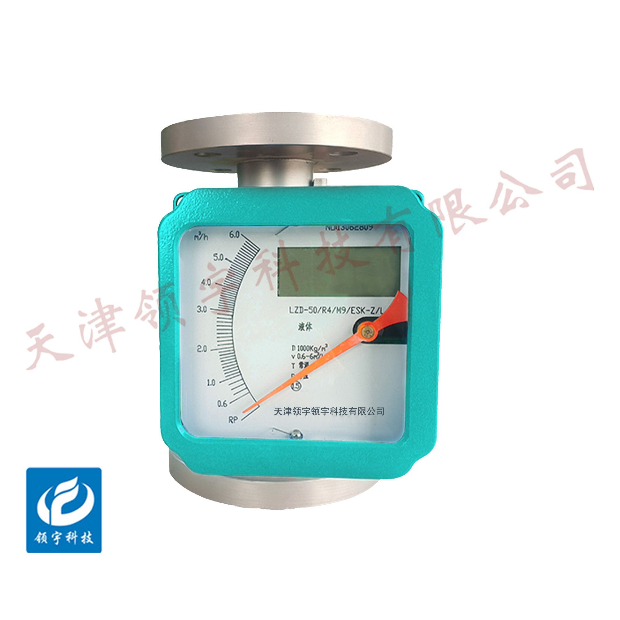
LF17-...4 Series Metal Rotameters
● Resistant to Harsh Operating Conditions: Its metal construction—such as stainless steel—endows it with high-pressure and high-temperature resistance, making it suitable for corrosive or high-temperature media in industrial sectors like petroleum and chemical processing.
● Ideal for small to medium flow rates: Based on the float-up principle, it offers higher measurement accuracy for low flow velocities and media flowing through small to medium pipe diameters (typically DN15–DN200), making it especially suitable for applications with unstable flow conditions.
● Easy installation and maintenance: Can be installed vertically without needing to reserve long straight pipe sections like turbine flowmeters; features a simple design with no complex moving parts inside, resulting in low maintenance costs.
● Intuitive readings: Traditional models feature a transparent conical tube with scale markings, allowing direct observation of the float position to measure flow rate; the smart version, meanwhile, supports digital display, making data acquisition even more convenient.
Key words:
Classification:
Download information:
Product Description
Product Overview Product overview
The LF17-... series of metal rotor flowmeters operates on the principle of variable-area measurement and is designed for continuous volumetric flow rate monitoring of liquids and gases in closed pipelines. These metal-tube float flowmeters boast a robust and reliable design, a wide operating temperature range, high accuracy, and an affordable price, making them suitable for a variety of applications. This series features intelligent on-site indication and is available in three installation configurations: bottom-in-top-out, left-in-right-out, and bottom-in-side-out. They are widely used in sectors such as defense, chemical processing, petroleum refining, metallurgy, power generation, environmental protection, pharmaceuticals, and light industry for measuring the flow rates of both liquids and gases.
Performance metrics TECHNICAL PARAMETERS
| Measurement range |
Water: 2.5–100,000 L/h |
| Air flow: 0.07–3000 m³/h |
|
| Temperature Ratio |
10:1 (DN < 100 mm) |
| 5:1 (DN > 100 mm) |
|
| Accuracy Level |
1.5, 1.0 |
| Maximum working pressure |
DN15, DN25, DN40, DN50 – 4.0 MPa |
| DN80, DN100, DN150 – 1.6 MPa |
|
| Medium temperature |
Standard type: -40°C—100°C |
| High-temperature type: -80°C to 250°C |
|
| F46 chloroplast lining: -40°C to -80°C; PFTE lining: -10°C to +120°C |
|
| Ambient temperature |
Pointer type: -40℃ ~ +65℃ |
| Intelligent model: -25°C to +65°C |
|
| Connection method |
Flange connections, threaded connections, and clamp connections |
| Electrical interface |
M20×1.5 (Custom orders available for special requirements) |
| Protection Level |
IP65 |
| Prevention and Protection Level |
Intrinsically Safe: ExibCT4 (PLB987S Safety Barrier) Flameproof: ExdIIBT4 |
| Medium viscosity |
DN15 ≤ 5 MPa·s, DN25–150 ≤ 250 MPa·s |
| Working power |
3.6V lithium battery, 1 unit, lasts for up to one year |
| +24VDC, ripple ≤5% |
|
| Measurement tube material |
304 stainless steel, 316 stainless steel, with a PTFE or F46 lining in either 304 or 316L stainless steel. |
| Rotor material |
304 or 316 (stainless steel); PTFE or F46 |
How it works Working Principle
The metal rotor flowmeter is a variable-area type, meaning that as the fluid flows upward through the meter’s vertical measuring tube, the float rises until the buoyant force acting on it exactly balances its weight. At this equilibrium point, the annular gap area between the float and the orifice plate (or tapered tube) remains constant. Notably, this gap area is directly proportional to the float’s rising height—thus, a specific float position corresponds to a particular flow rate. As the float moves up and down, its position is transmitted externally via magnetic coupling to a remote indicator, causing the indicator’s pointer to follow the float’s movement. Additionally, a cam mechanism ensures that the pointer provides a linear indication of the actual flow rate. For the electrically remote-transmitted version, while the pointer visually displays the flow rate on-site, an angular displacement sensor combined with an electronic transmitter circuit precisely converts the flow signal into a standardized 4–20mA output.

External dimensions APPEARANCE OF SIZE

| Vertical installation dimension | |||||
| Nominal Diameter (mm) | Instrument Pressure Resistance | D 0 | D | f | n-Φd |
| DN 15 | 4.0 | 65 | 95 | 224 | 4-Φ14 |
| DN 25 | 4.0 | 85 | 115 | 245 | 4-Φ14 |
| DN 40 | 4.0 | 110 | 150 | 266 | 4-Φ18 |
| DN 50 | 4.0 | 125 | 160 | 285 | 4-Φ18 |
| DN 80 | 1.6 | 160 | 195 | 306 | 8-Φ18 |
| DN 100 | 1.6 | 180 | 215 | 336 | 8-Φ18 |
| DN 150 | 1.6 | 240 | 280 | 366 | 8-Φ18 |
Installation Requirements INSTALLATION
1. Installation Location and Flow Direction
- Must be installed vertically, with the fluid flowing upward through the instrument; the tilt angle should not exceed 5° (otherwise, the float may easily become stuck, leading to a significant increase in measurement error).
- The upstream section must include a straight pipe segment of at least 5 times the pipe diameter, while the downstream section requires a straight run of at least 2 times the pipe diameter—this ensures that valves and elbows aren’t placed too close to each other, preventing turbulence in the flow field.
- The installation environment should be kept away from strong magnetic fields, sources of severe vibration, and areas exposed to high temperatures and radiation, to prevent damage to instrument components or signal interference.
2. Fluid Condition Adaptation
- Fluid temperature and pressure must not exceed the instrument's rated range, as doing so could lead to deformation of the metal tube or jamming of the float.
- If the fluid contains impurities, particles, or viscous substances, a filter must be installed upstream of the instrument (with filtration accuracy determined by the float gap) to prevent blockage of the annular passage.
3. Connection and Sealing Requirements
- When using flanged or threaded connections, ensure the coaxial alignment of the pipe and instrument to prevent stress caused by forced misalignment.
- Sealing gaskets must be made from materials suitable for the fluid being handled (e.g., metal gaskets for high-temperature applications, PTFE gaskets for corrosive fluids) to prevent leaks that could affect measurement accuracy.
Previous Page
Next Page
Previous Page
Next Page
Related Products
Product inquiry
If you are interested in our products, please leave your e-mail, we will contact you as soon as possible, thank you!
Tianjin Ling Yu Technology Co., Ltd.
Operator:86-22-58554679
Fax: 022-58285528
Manager Ding: 86-18902041592
WhatsApp:8618902041592
Complaint Hotline:86-15822286986
Factory Address: No.5 Yingbin Road, Xiqing District, Tianjin
E-mail:sales@lingyukeji.com
Purchasing Department E-mail:lykj_tj@163.com
WhatsApp Scan

Copyright©2022 Tianjin Ling Yu Technology Co., Ltd