

Product display

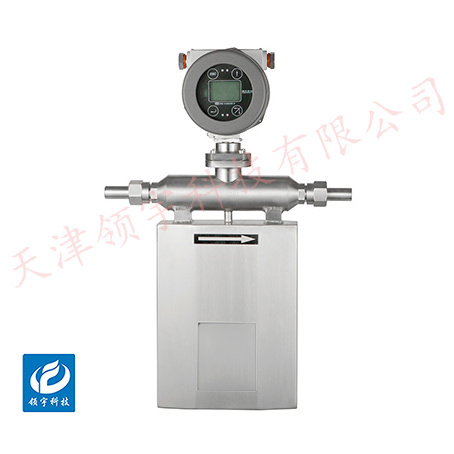


LF-16U Series U-Type Mass Flow Meter
● Measures gas mass flow without requiring temperature or pressure compensation
● Large range ratio, measuring flow velocity range: 0.1 Nm/s to 120 Nm/s. ■ No pressure loss, suitable for pipes of any shape with known cross-sectional areas.
● Corrosion-resistant sensors, ideal for measuring corrosive gases. The insertion-type sensor allows for convenient online installation and maintenance.
● The expert algorithm covering the full measurement range ensures high accuracy, making it suitable for trade settlement or gas leak detection.
Key words:
Classification:
Download information:
Product Description
Product Overview Product overview
The LF-16 series mass flow meter is a high-precision measuring device capable of directly detecting the mass flow rate of fluids—whether liquids, gases, or multiphase flows. Its key advantage lies in its ability to provide accurate mass flow data without requiring compensation for parameters such as temperature or pressure, effectively eliminating measurement errors caused by fluid density variations that often plague conventional volumetric flow meters.
Performance Metrics TECHNICAL PARAMETERS
Measuring the density range |
0~2 g/cm³ |
Accuracy and Precision |
0.1~0.2 |
Repetitiveness |
0.1–0.25% |
Converter format |
Wall-mounted type, on-site type |
Nominal Diameter |
DN6-DN200 |
Measuring medium |
In addition to uniformly flowing fluids with normal viscosity, it can also measure high-viscosity fluids (such as honey, oil pastes, etc.); moreover, it is not limited to measuring just a single The fluid parameters of the solution can also measure multiphase flows. |
Medium temperature |
-50℃ to 200℃ |
Material |
Measurement tube made of 316L stainless steel, outer casing made of 304 stainless steel |
Work stress |
0–4 MPa |
Power Supply |
220V AC ±10%, 50Hz or 24V DC ±5% |
Explosion-proof rating |
Exd (ia)ⅡCT6GB |
Signal Output |
Pulse output, 4-20mA current output, and optional RS485 output |
Measurements show |
Instantaneous flow rate, cumulative flow rate, density, temperature |
Sensor Protection Rating |
IP65 (wall-mounted type), IP67 (field-type) |
How it works Working Principle
The principle behind mass measurement in Coriolis mass flowmeters is Newton's Second Law, F = Ma. When a fluid flows through the vibrating tube, it generates a Coriolis force that is directly proportional to the mass flow rate. If no fluid is flowing, the vibrating tube remains untwisted, and the electromagnetic signal detectors on either side of the tube pick up signals that are in phase. However, when fluid passes through, the vibrating tube twists under the influence of the torque, creating a phase difference between the two detectors. The transmitter measures the time lag between the left and right detection signals, and multiplying this time difference by the flow calibration coefficient allows it to determine the mass flow rate accurately.
The density measurement principle of a Coriolis mass flowmeter is based on the fact that the vibration frequency is inversely proportional to the square root of the fluid density—thus, by measuring the vibration frequency, the fluid density can be determined. Therefore, a mass flowmeter can simultaneously measure both the mass flow rate and the density of the fluid.
External dimensions APPEARANCE OF S

Installation Requirements INSTALLATION
1. The flowmeter can be installed on horizontal, vertical, or inclined pipelines and positioned at any angle around the pipe circumference—provided ease of replacement and maintenance is considered. For dirty or moist gases, it is recommended to install the flowmeter horizontally (pointing upward) to minimize the risk of sensor contamination. Additionally, the sensor should be mounted away from the lowest point of the pipeline to prevent water accumulation inside the pipe, which could interfere with the proper operation of the flowmeter.
2. The straight pipe section requires 5 times the diameter (D) upstream and 3 times the diameter (D) downstream. However, when a gas rectifier is installed or the gas flow rate is below 30 m/s, the requirements can be reduced to 3 times D upstream and 2 times D downstream.
3. In explosion-proof areas, open flames or pipelines made of non-weldable materials are prohibited. Instead, dedicated clamps can be used to securely attach sensors to the pipes. In explosion-proof zones, use a manual drill to create holes, while in safe areas, an electric drilling tool is recommended.
4. The arrow on the sensor housing should point toward "1," aligning with the direction of gas flow. The sensor should be inserted perpendicular to the direction of gas flow.
Previous Page
Next Page
Previous Page
Next Page
Related Products
Product inquiry
If you are interested in our products, please leave your e-mail, we will contact you as soon as possible, thank you!
Tianjin Ling Yu Technology Co., Ltd.
Operator:86-22-58554679
Fax: 022-58285528
Manager Ding: 86-18902041592
WhatsApp:8618902041592
Complaint Hotline:86-15822286986
Factory Address: No.5 Yingbin Road, Xiqing District, Tianjin
E-mail:sales@lingyukeji.com
Purchasing Department E-mail:lykj_tj@163.com
WhatsApp Scan

Copyright©2022 Tianjin Ling Yu Technology Co., Ltd