

Product display

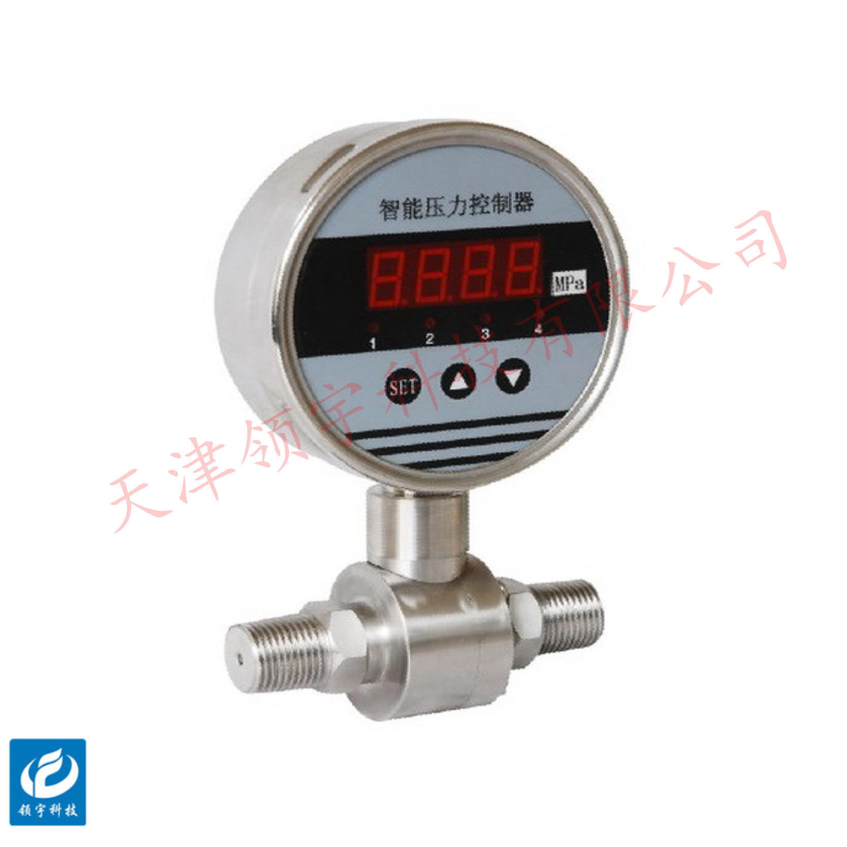
LPS—N3C Smart Differential Pressure Switch
● Multiple-channel digital output
● Display pressure values directly on-site
● Multiple alarm methods can be set.
● Set action values with buttons
Key words:
Classification:
Download information:
Product Description
Product Overview Product overview
The LPS-N3C series electronic differential pressure switch is a next-generation, intelligent product capable of measuring the pressure difference in on-site pipelines and pressure vessels. It features local display, switch-action output, and remote signal transmission, making it convenient for downstream control systems to collect data. The local switch output is a dry-contact SPDT type, while the analog output supports signals such as 4-20mA current and RS485 communication. Compared to mechanical pressure switches, this model offers exceptional ease in adjusting setpoints. Additionally, it allows users to configure multiple alarm modes, including single-point alarms, alarms triggered when the pressure falls within or outside preset upper and lower limits. This versatile device is widely used in industries such as petroleum, chemical processing, metallurgy, power generation, sugar production, pharmaceuticals, and other sectors where precise pressure control is essential.
Performance Metrics TECHNICAL PARAMETERS
Power supply: 18–32 VDC, typical value: 24 VDC
Measurement media: oil, water, gas, and other media compatible with stainless steel;
Measurement range: 0–0.1–2.5 MPa (higher requirements can be customized)
Measurement accuracy: 0.25%FS, 0.5%FS; (Higher accuracy available upon request)
Overload capacity: 2 times full-scale pressure:
Analog output: 4-20mA;
Switch output: 2-channel SPDT relay / 4-channel SPDT relay
Contact capacity: 250VAC, 3A / 24VDC 1.5A;
Communication method: RS485 (optional);
Load capability: Current type ≤500Ω, voltage type ≥250kΩ;
Threaded connection: M20×1.5 (customizable based on site requirements);
Electrical interface: Wiring exits from the rear terminals on the panel; (for select models, wiring can optionally be routed via a side-mounted M12*1 connector).
Temperature Drift Coefficient: Within the specified operating temperature range, for every 10°C change in ambient temperature, the output variation is ≤ ±0.05% of the full scale; annual drift < ±0.3%.
Long-term stability: ±0.1%FS/year;
Housing material: Stainless steel housing
Housing Protection: IP65
Operating temperature: -20~85°C
Storage temperature: -40~100°C
Relative humidity: 0–95% RH
External dimensions APPEARANCE OF SIZE

Installation Requirements INSTALLATION
1. The pressure controller can be directly installed onto the component being tested. To facilitate installation and maintenance, it is recommended to add a shut-off valve between the component and the pressure controller. In environments with significant vibration or shock, a flexible hose can be connected to the pressure controller’s fitting to achieve mechanical decoupling.
2. A sealing ring should be installed between the pressure controller connector and the pipe fitting or shut-off valve. For flush-head pressure controllers, the internal thread depth of the pipe fitting or shut-off valve must exceed 25 mm.
3. In general, the pressure controller should be installed vertically, facing upward relative to the horizontal surface. During installation, use a wrench to tighten the controller by turning the hexagonal nut located at the bottom of the pressure controller.
4. When the measurement range is less than 100 kPa, it must be installed vertically.
Note: For areas prone to frequent lightning strikes, it is recommended to install lightning protection devices along the lines.
Previous Page
Next Page
Previous Page
Next Page
Related Products
Product inquiry
If you are interested in our products, please leave your e-mail, we will contact you as soon as possible, thank you!
Tianjin Ling Yu Technology Co., Ltd.
Operator:86-22-58554679
Fax: 022-58285528
Manager Ding: 86-18902041592
WhatsApp:8618902041592
Complaint Hotline:86-15822286986
Factory Address: No.5 Yingbin Road, Xiqing District, Tianjin
E-mail:sales@lingyukeji.com
Purchasing Department E-mail:lykj_tj@163.com
WhatsApp Scan

Copyright©2022 Tianjin Ling Yu Technology Co., Ltd