

Product display

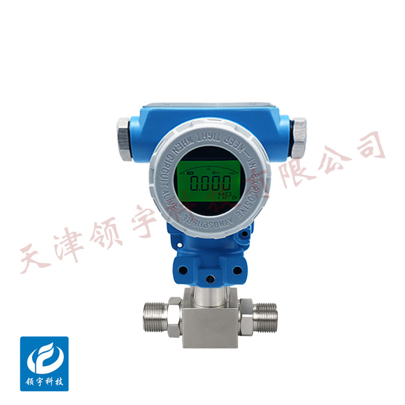
LPT-11 Differential Pressure Transmitter
● High-quality diffused silicon piezoresistive sensing element
● Multiple signal outputs available
● Supports HART protocol (please specify when ordering)
●Isolated Circuit Design
● Equipped with overcurrent and overvoltage protection features
●Anti-pulsation Pressure Shock
Key words:
Classification:
Download information:
Product Description
Product Overview Product overview
The LPT-11 series differential pressure transmitters feature a modular design, consisting of a sensor module and an amplifier module. The sensor section converts the differential pressure signals from two independent chambers into differential capacitance, which is then processed by the amplification circuitry and transmitted as a standard industrial signal. Typically, differential pressure transmitters are used in the following three applications: 1. Combined with throttling devices, they measure flow rates—such as gas, steam, or liquid flow (both volumetric and mass flow)—by calculating fluid velocity based on the pressure difference generated before and after the throttling element. 2. They utilize the pressure difference caused by the weight of a liquid to determine the liquid's height. 3. They directly measure the pressure difference between two separate pipelines or sealed containers equipped with backpressure, enabling the calculation of liquid level height.
Performance Metrics TECHNICAL PARAMETERS
| Instrument indicators | Standard Type | Explosion-proof type |
| Measurement range | 0..0.02~2.5 MPa | 0..0.02~2.5 MPa |
| Overload Capacity | 150% | 150% |
| Maximum Static Pressure | 20MPa | 20MPa |
| Stability | <0.2%/year | <0.2%/year |
| Power supply | 12-30VDC | 12-30VDC |
| Load Capacity | <(u-12)/0.02 | <(u-12)/0.02 |
| Diaphragm | 316L Stainless Steel | 316L Stainless Steel |
| O-ring | Fluororubber | Fluororubber |
| Ambient temperature | -20~70℃ | -20~70℃ |
| Relative humidity | ≤80% | ≤80% |
| Explosion-proof rating | Exd ll CT6Gb | Exd ll CT6Gb |
| Protection Level | IP65 | IP65 |
| Medium temperature | -20~80℃ | -20~80℃ |
External dimensions APPEARANCE OF SIZE

Installation Requirements INSTALLATION
1. The pressure transmitter can be directly installed on the pipe component being measured. To facilitate installation and maintenance, it is recommended to install a shut-off valve between the pipe component and the pressure transmitter. In environments with significant vibration or shock, a flexible hose can be connected to the pressure transmitter’s fitting to achieve mechanical decoupling.
2. A sealing ring should be installed between the pressure transmitter connector and the pipe fitting or shut-off valve. For flush-head pressure transmitters, the internal thread depth of the pipe fitting or shut-off valve must exceed 25 mm.
3. In general, the pressure transmitter should be installed vertically, facing upward relative to the horizontal plane. During installation, use a wrench to tighten the transmitter by turning the hexagonal nut at its base—avoid directly twisting the upper part of the transmitter.
Note:
1. Do not poke the pressure port with sharp or hard objects, as this may damage the sensor’s pressure diaphragm. Additionally, since the pressure diaphragm is permanently integrated with the housing, the device will become irreparable if damaged. Furthermore, product quality issues caused by improper use—such as accidental pressing of the diaphragm, static overloading due to particulate-containing media, or dynamic pressure shocks—are not covered under our warranty. Therefore, users are strongly advised to take extra care in protecting the diaphragm during both installation and operation.
2. For areas prone to frequent lightning strikes, it is recommended to install lightning protection devices along the lines.
Previous Page
Previous Page
Related Products
Product inquiry
If you are interested in our products, please leave your e-mail, we will contact you as soon as possible, thank you!
Tianjin Ling Yu Technology Co., Ltd.
Operator:86-22-58554679
Fax: 022-58285528
Manager Ding: 86-18902041592
WhatsApp:8618902041592
Complaint Hotline:86-15822286986
Factory Address: No.5 Yingbin Road, Xiqing District, Tianjin
E-mail:sales@lingyukeji.com
Purchasing Department E-mail:lykj_tj@163.com
WhatsApp Scan

Copyright©2022 Tianjin Ling Yu Technology Co., Ltd