

Product display


LPT-S High-Precision Pressure Transmitter
● High-performance monocrystalline silicon core
●24-bit high-precision ADC
● Wide range of transferability
● Can be configured via HART handheld device
● Dual Compensation for Circuit and Core
● Output damping is adjustable
● Available with an ultra-low temperature drift type (20 ppm/℃ typical)
● Equipped with RS485 functionality (please specify when ordering)
Key words:
Classification:
Download information:
Product Description
Product Overview Product overview
The LPT-S series intelligent pressure transmitters feature a microprocessor-based, modular circuit design that delivers excellent anti-interference performance. Equipped with a built-in temperature sensor for transmitter compensation, these devices enhance measurement accuracy while minimizing temperature drift. They also boast outstanding long-term stability, high reliability, and robust self-diagnostic capabilities. Users can easily calibrate, configure, and set up the transmitters using a HART-compatible handheld communicator. The interface includes distinct password-protected function sections, allowing users to conveniently customize settings. These transmitters are widely used in industries such as chemical processing, metallurgy, water management, power generation, and petroleum applications.
Performance metrics TECHNICAL PARAMETERS
| Measuring medium | Gas, liquid, vapor | ||
| Measurement range | Minimum range (kPa) | Measurement range and sensor limit values (kPa) | |
| Maximum range (URL) | Minimum Range (LRL) | ||
| 1.0 | 6.0 | -6.0 | |
| 4.0 | 40 | -40 | |
| 10.0 | 100 | -100 | |
| 12.5 | 250 | -100 | |
| 25.0 | 500 | -100 | |
| 25.0 | 1000 | -100 | |
| 87.5 | 3500 | -100 | |
| Measurement range ratio: | 40:1 | ||
| Accuracy | Class 0.075, Class 0.1 (including linearity, hysteresis, and repeatability) | ||
| Impact of the range ratio: | Class 0.075 | When the range ratio is 1:1 to 10:1, adjust the range to ±0.05%; | |
| When the range ratio exceeds 10:1, it is ±[0.0075 × range ratio]%; | |||
| Class 0.1, Class 0.2 | With a range ratio of 1:1 to 10:1, the calibration range is ±0.1%. | ||
| When the range ratio exceeds 10:1, it is ±[0.05 + 0.005 × range ratio]%; | |||
| Stability | Class 0.075 | The error over 36 months is ±0.15% of the full scale. | |
| Class 0.1 | The error over 36 months is ±0.2% of the full scale. | ||
| Class 0.2 | The error over 36 months is ±0.25% of the full scale. | ||
| Temperature affects | Class 0.075 | Zero-point or span error is ±0.15% of the full scale, per 28°C. | |
| Class 0.1 | Zero-point or span error is ±0.2% of the full scale, per 28°C. | ||
| Class 0.2 | Zero-point or span error is ±0.25% of the full scale, per 28°C. | ||
| Power supply impact | Less than ±0.005%/V of the calibration range | ||
| Vibration Impact | Less than ±0.05%/g of the maximum range | ||
| Installation Impact | Zero drift is no more than 0.25 kPa, and this error can be eliminated by zeroing—without affecting the measurement range. | ||
| Hydrostatic Pressure Impact | ±0.05% URL/10 MPa | ||
| Output signal | 4-20mA + HART (can also feature RS485) | ||
| Power supply | 15-36VDC | ||
| Ambient temperature: | -40°C to 85°C | ||
| Medium temperature | -40°C to 120°C | ||
| Storage temperature | -40°C to 85°C | ||
| Display | 7-digit LCD display | ||
| Protection Level | IP65 | ||
| Explosion-proof rating | Exd IIC T6Gb | ||
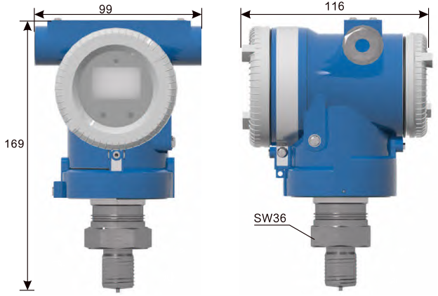
External dimensions APPEARANCE OF SIZE
Installation Requirements INSTALLATION
The pressure transmitter can be directly mounted onto the pipeline using an M20×1.5 external thread or other types of threads, or it can be installed via a impulse line and mounting bracket.
Notes for pressure-tube installation:
1. The pressure-tapping line should be as short as possible and installed in a location with minimal temperature fluctuations and where deposits are unlikely to form.
2. To minimize the effects of friction and prevent clogging, use a pressure-tapping tube with an adequately large diameter.
3. During high-pressure measurements, the pressure-tapping tube must have sufficient high-pressure resistance strength.
4. The pressure-tapping tube should be installed at an angle to allow gas to escape from the liquid medium, or liquid to flow out of the gas medium.
Previous Page
Previous Page
Related Products
Product inquiry
If you are interested in our products, please leave your e-mail, we will contact you as soon as possible, thank you!
Tianjin Ling Yu Technology Co., Ltd.
Operator:86-22-58554679
Fax: 022-58285528
Manager Ding: 86-18902041592
WhatsApp:8618902041592
Complaint Hotline:86-15822286986
Factory Address: No.5 Yingbin Road, Xiqing District, Tianjin
E-mail:sales@lingyukeji.com
Purchasing Department E-mail:lykj_tj@163.com
WhatsApp Scan

Copyright©2022 Tianjin Ling Yu Technology Co., Ltd