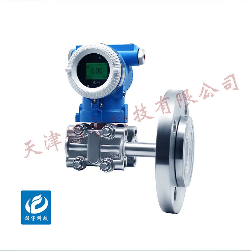
Product display
LPT-LS Single-Flange Pressure Transmitter
● High-performance monocrystalline silicon core
●24-bit high-precision ADC
● Core and Circuit Dual Compensation
● Can be configured via HART handheld device
● Multiple remote transmission devices available for low-pressure measurement
● Output damping is adjustable
● Equipped with RS485 functionality (please specify when ordering)
Key words:
Classification:
Download information:
Product Description
Product Overview Product overview
The LPT-LS series single-flange pressure/level transmitters feature a microprocessor-based, modular circuit design that delivers excellent anti-interference performance. They are equipped with a built-in temperature sensor for transmitter compensation, enhancing measurement accuracy while minimizing temperature drift. These transmitters also boast outstanding long-term stability, high reliability, and robust self-diagnostic capabilities. Users can easily calibrate, configure, and set up the transmitters using a HART-compatible handheld communicator. The interface includes function sections with varying password permissions, allowing users to conveniently customize settings. Additionally, the low-pressure models come with multiple configurable interfaces, making them perfectly suited for both closed and open containers. For applications involving viscous or corrosive media, transmitters made from specialized materials are available. This versatile product line is widely used in industries such as chemical processing, metallurgy, water management, power generation, and petroleum production.
Performance Metrics TECHNICAL PARAMETERS
| Measuring medium | Gas, liquid, vapor | ||
| Measurement Range (*Involves secondary encapsulation with oil; measurement range and flange specifications must be verified.) |
Minimum range (kPa) | Measurement Range and Sensor Limit Values (kPa) | |
| Maximum Range (URL) | Minimum Range (LRL) | ||
| 1.0 | 6.0 | -6.0 | |
| 4.0 | 40 | -40 | |
| 10.0 | 100 | -100 | |
| 12.5 | 250 | -100 | |
| 25.0 | 500 | -100 | |
| 25.0 | 1000 | -100 | |
| 87.5 | 3500 | -100 | |
| Measurement range ratio: | 40:1 | ||
| Precision | Class 0.2, Class 0.5 (including linearity, hysteresis, and repeatability) | ||
| Range ratio impact: | Class 0.2 | When the range ratio is 1:1 to 10:1, the calibration accuracy is ±0.20% of the span. | |
| When the range ratio exceeds 10:1, it is ±[0.03 × range ratio - 0.1]%; | |||
| Stability | Class 0.2 | The error over 36 months is ±0.25% of the full scale. | |
| Temperature Influence | Class 0.2 | Zero-point or span error is ±0.25% of the full scale at 28°C. | |
| Power supply impact | Less than ±0.005%/V of the calibration range | ||
| Vibration Impact | Less than ±0.05%/g of the maximum range | ||
| Installation Impact | Zero drift is no more than 0.25 kPa; this error can be eliminated by zero adjustment without affecting the measurement range. | ||
| Static Pressure Influence | Zero-point impact | ±0.1% URL/10 MPa | |
| Measurement Range Influence | ±0.2% URL/10 MPa | ||
| Output signal | 4-20mA + HART (can simultaneously support RS485) | ||
| Power Supply | 15-36VDC | ||
| Ambient temperature: | -40℃ to 85℃ | ||
| Medium temperature | -40℃ to 120℃ | ||
| Storage Temperature | -40℃ to 85℃ | ||
| Display | 7-digit LCD display | ||
| Protection Level | IP65 | ||
| Explosion-proof rating | Exd IIC T6Gb | ||
External dimensions APPEARANCE OF SIZE
Materials are being prepared...
Installation Requirements INSTALLATION
Note:
1. Please ensure that the inner diameter of the gasket used is larger than the inner diameter of the diaphragm seal. If the gasket’s inner diameter is smaller than that of the diaphragm seal, it may affect the proper functioning of the diaphragm, leading to errors or even damaging the diaphragm.
2. Be careful not to damage the membrane surface—placing the membrane face down may cause harm to its surface.
3. Do not bend, squeeze the capillary tube, or apply excessive pressure to it.
4. Do not loosen the four screws on the chamber flange (if the filling fluid leaks, the transmitter will stop working).
5. Install the flange diaphragm on the high- and low-pressure sides of the liquid tank, as indicated by the H and L labels.
6. To avoid measurement errors caused by temperature differences, the capillary tubes can be bundled together. The capillaries must be securely fixed to the tank wall to prevent interference from wind and vibrations. If the capillaries are too long, they should be coiled up and secured with clips.
Note:
Open the transmitter display cover; the display screen can rotate 330° and is adjustable after installation, ensuring optimal readability of the on-site display unit. Note that the connecting cable behind the display should not be overrotated.
Previous Page
Next Page
Previous Page
Next Page
Related Products
Product inquiry
If you are interested in our products, please leave your e-mail, we will contact you as soon as possible, thank you!
Tianjin Ling Yu Technology Co., Ltd.
Operator:86-22-58554679
Fax: 022-58285528
Manager Ding: 86-18902041592
WhatsApp:8618902041592
Complaint Hotline:86-15822286986
Factory Address: No.5 Yingbin Road, Xiqing District, Tianjin
E-mail:sales@lingyukeji.com
Purchasing Department E-mail:lykj_tj@163.com
WhatsApp Scan

Copyright©2022 Tianjin Ling Yu Technology Co., Ltd


